AutoFlag
Vision-assisted flag actuation
An embedded electromechanical system for a recreational boating flag. Camera observations and vessel motion inform a rider-down decision, while persistent manual override keeps the operator in control. I designed the enclosure, actuator mounting, component integration, and control behavior.
Manual actuation demonstrated · Automatic boat operation in development
Observe
Camera
GNSS speed
Compass heading
Interpret
Human detection
Motion analysis
Sensor evidence
Decide
Fusion + debounce
Rider-down latch
Recovery conditions
Sequence
Motor / servo PWM
Encoder feedback
Limits + timeouts
Deploy
Rack-and-pinion concept
Flag extension
Pole positioning
Manual mode persists until released
01 / Computing architecture
Two processors, one board
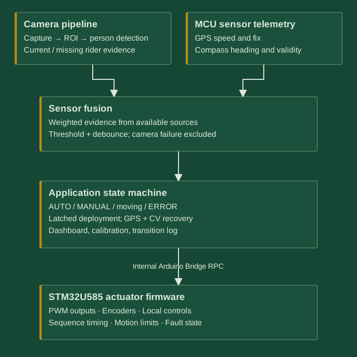
The UNO Q Linux MPU runs camera capture, computer vision, sensor fusion, and the operating state machine. Its onboard STM32U585 handles physical I/O and actuator sequencing. Arduino Bridge carries commands, calibration, and telemetry between them.
Perception and decisions
Python / OpenCV · Local web dashboard · Configuration · Transition logging
Processes camera frames and sensor observations, selects an operating state, and issues actuator commands.
Physical control
PWM outputs · Quadrature encoders · UART / I²C sensors · Local inputs
Enforces the motion sequence, individual motor endpoints, soft limits, and motor-motion timeouts.
Software modules and communication contract
The application separates camera management, detector backends, ROI processing, sensor fusion, state management, transport, configuration storage, and event logging. Bridge methods expose heartbeat, command, settings, and telemetry calls. An external ESP32 is not part of this primary architecture.
02 / Detection & control
Evidence before actuation
Camera observations, GPS speed loss, and compass-heading changes contribute to a weighted rider-down score. Only available sources are normalized into the decision, and the configured threshold must persist through a debounce interval.
Human-presence detection
The pipeline supports ROI-limited person detection using a local ONNX model when available, with an OpenCV HOG fallback. The installed model and its boat-scene accuracy are not established by source review.
Motion context
GPS tracks a towing-speed baseline and subsequent speed drop. Compass heading change and heading rate provide additional evidence, rather than proof of a fall.
Unavailable inputs
A camera failure removes CV from fusion rather than being interpreted as a rider disappearing. Detection describes presence, not identity recognition.
Deploy and latch
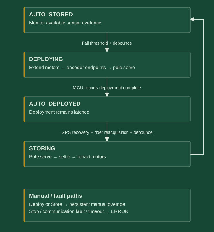
Once a rider-down condition is inferred, deployment stays latched. A reduction in the score cannot silently store the flag.
Recover deliberately
Automatic storage requires GPS speed recovery from the post-fall minimum and current positive rider detection, followed by recovery debounce.
Preserve manual control
App and physical Deploy/Store commands enter persistent manual override. Automatic scores cannot undo an active manual command.
Operating-state diagram
03 / Electromechanical system
Sequenced deployment and retraction
The flexible rack-and-pinion concept extends and retracts the flag through motorized motion, with a separate servo stage for pole positioning. The enclosure and dedicated actuator mount connect that mechanism to the electronics and operator controls.
- Extend both motor channels
Each channel stops independently at its calibrated encoder endpoint.
- Command the pole servo
After extension, move to the deployed angle and allow the configured settling interval.
- Return the pole servo
Command the stored angle and allow settling before retraction.
- Retract the motor channels
Stop each channel at its retracted encoder endpoint.
Motion supervision and fault behavior
- Communication loss
- The MCU has a 2.5-second heartbeat timeout for remote motion when physical override is not active. The application enters ERROR on lost controller communication.
- Motion limits
- Encoder soft limits and motor-motion timeouts are implemented in firmware. The application also supervises deployment/storage time.
- Stop behavior
- Local Stop is handled on the MCU. Motor PWM stop is distinct from actuator power isolation; the servo angle is commanded, not independently confirmed by closed-loop position feedback.
04 / Electrical architecture
Signal interfaces and actuator power
The firmware assigns separate interfaces for navigation sensors, local controls, encoder feedback, and PWM outputs. Actuator power is separate from the controller’s signal I/O.
Sensor paths
Camera into the Linux video pipeline; GPS over UART; compass over I²C.
Motion paths
PWM commands to external drivers, with quadrature feedback and active-low physical controls.
Power boundary
3.3 V signal I/O and separate fused actuator supply are specified in the firmware documentation. Installed driver models and supply sizing still need as-built confirmation.
Firmware signal diagram and pin assignments
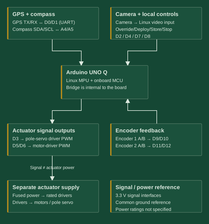
| Function | Pins / interface |
|---|---|
| GPS TX / RX | D0 / D1 · 9600 baud UART |
| Override / Deploy | D2 / D4 · Active-low inputs |
| Store / Stop | D7 / D8 · Active-low inputs |
| Pole servo | D3 · PWM command |
| Motor drivers 1 / 2 | D5 / D6 · Servo-style PWM |
| Encoder 1 A / B | D9 / D10 |
| Encoder 2 A / B | D11 / D12 |
| Compass SDA / SCL | A4 / A5 · I²C |
| Camera | Linux video device |
05 / Validation
Manual actuation demonstrated
The mechanism has moved under manual control on hardware. Automatic operation on a boat is still in development.
- Demonstrated
- Physical actuation from manual control.
- Implemented in source
- Perception interfaces, fusion, state management, command sequencing, and fault-control paths for the UNO Q target.
- Remaining verification
- Actual deployed hardware configuration, rider-detection reliability, repeated boat deployment, and environmental performance.
Software implementation was AI-assisted. The project emphasizes my mechanical design, component integration, and control-definition work.