Munnin
Modular unmanned aircraft system
Project Lead · Systems Integration · Mechanical Design
I lead Munnin’s development across airframe, propulsion, avionics, communications, and compute. My detailed mechanical work includes the main body, top plate, motor mounts, landing gear, and battery retention. I coordinate subsystem interfaces as the team brings the aircraft into its initial hardware build.
Initial hardware build · 2026–present
01 / Airframe architecture
Structures and interfaces
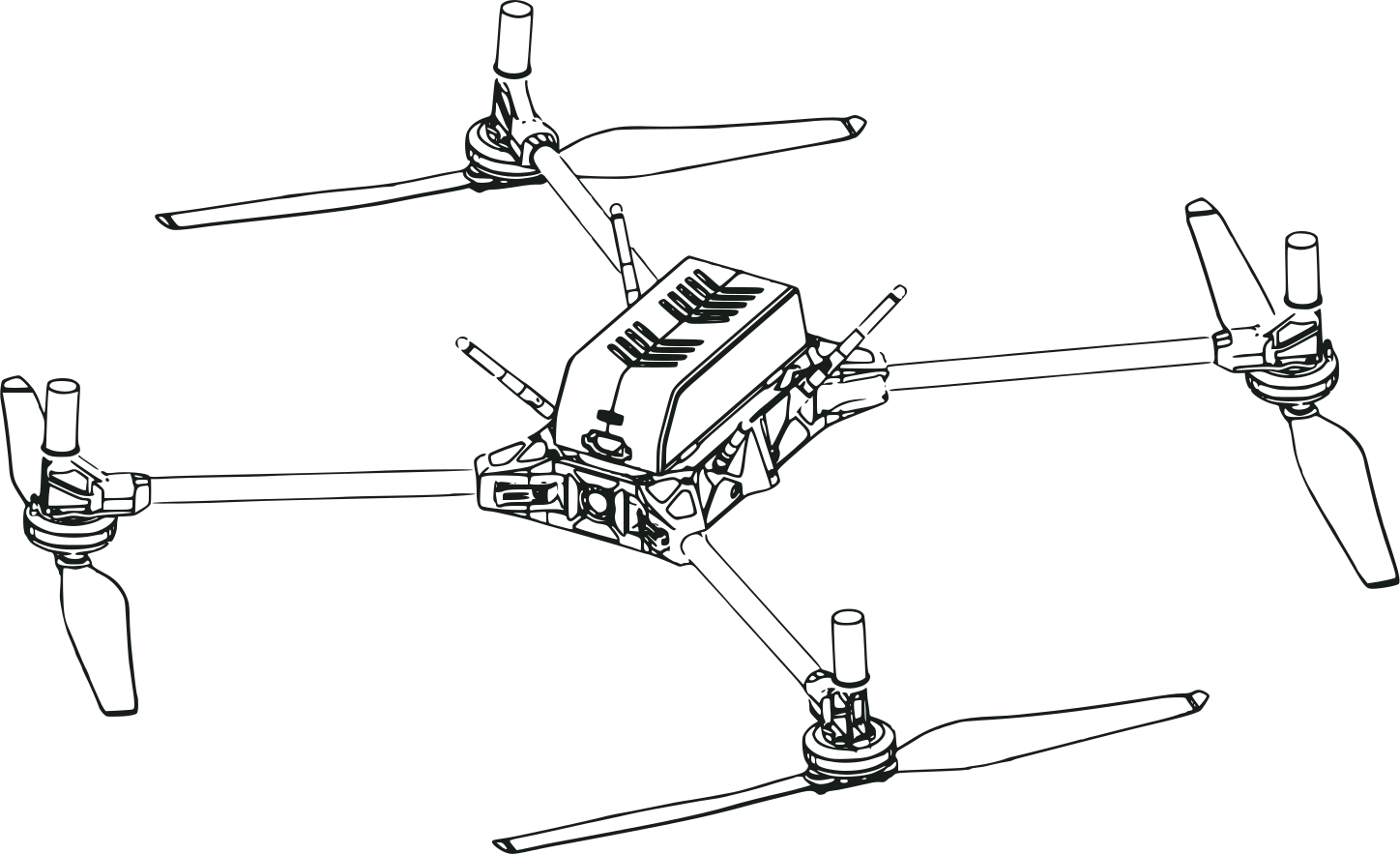
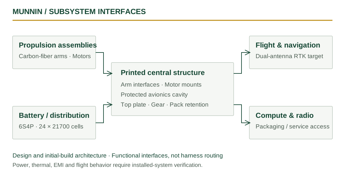
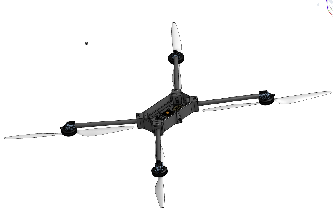
I structured the airframe around a printed main body, carbon-fiber arm assemblies, and replaceable external parts. The body connects the arm interfaces, protected avionics volume, top plate, and landing-gear inserts. The design packages a 22-inch propeller envelope around a printed central structure.
Central body
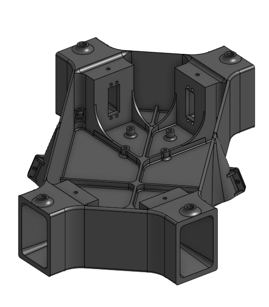
A single PAHT-CF print carries the arm interfaces and provides a protected cavity for electronics. Internal tray and stiffener interfaces connect packaging requirements to the body geometry.
Folding arms
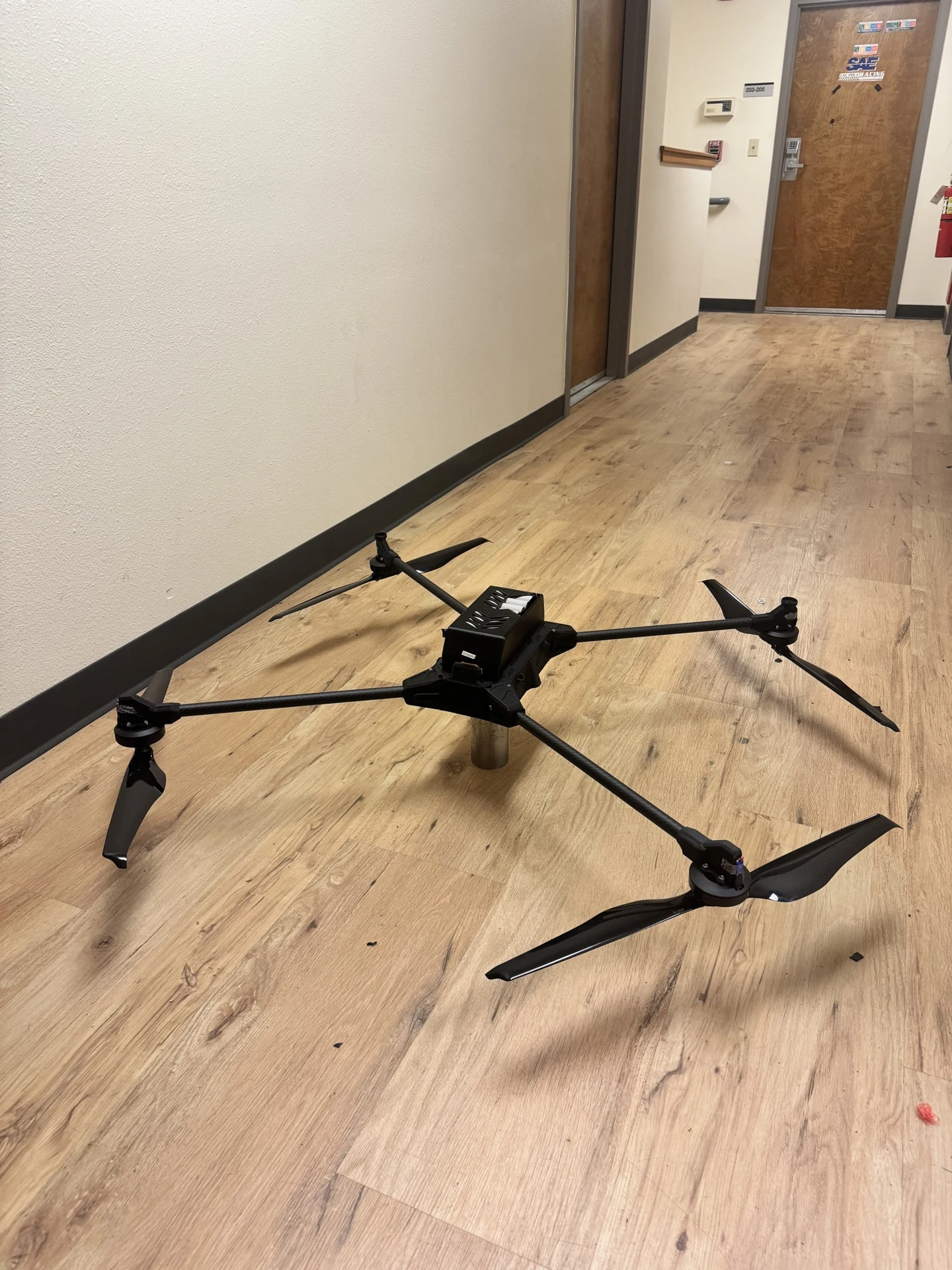
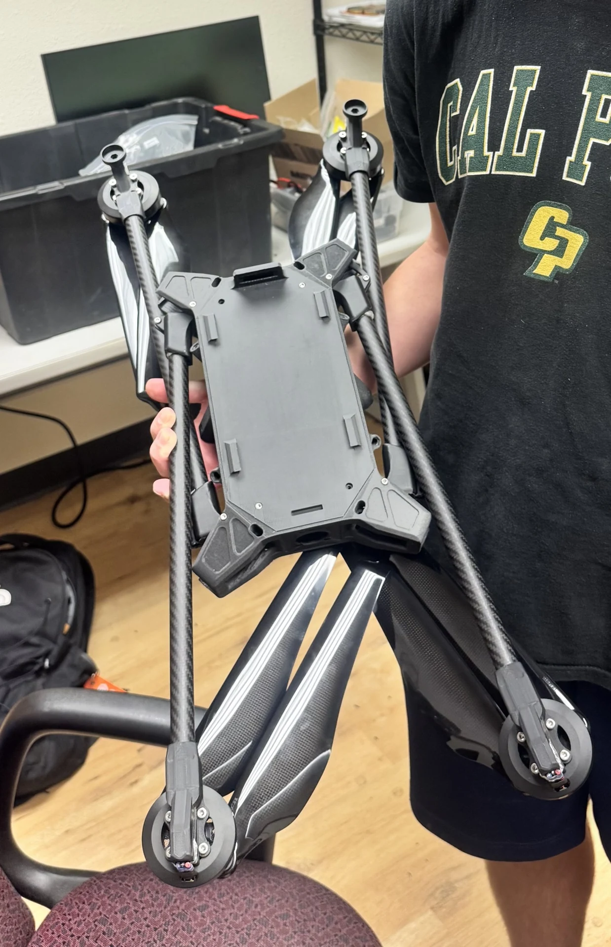
The aircraft progressed from plug-in, removable arms to the folding configuration shown in the hardware below. Lock stiffness, retention, and folded clearance are the relevant interface checks.
Replaceable external parts
I designed the motor mounts and landing-gear inserts as separate, replaceable parts. The mounts connect propulsion loads to the carbon-fiber arms. The gear insert is intended to absorb damage before the main body during a hard landing.
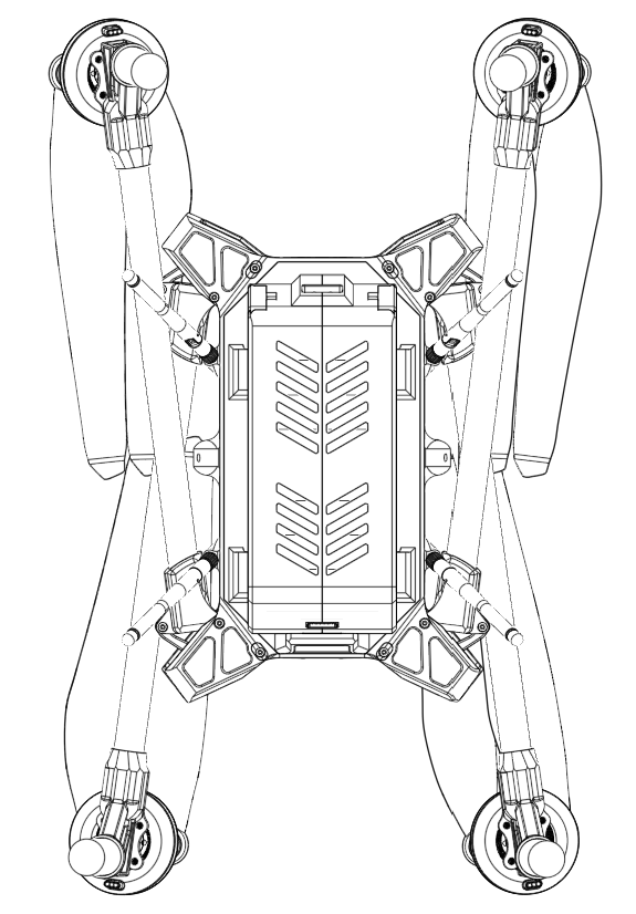
Earlier retention architecture and folded-envelope drawing
The earlier removable-arm design used a plug-in socket and M3 thumb-screw retention with axial preload. The folding revision changes that interface; earlier retention geometry should not be read as the final folding lock.
02 / Materials & manufacturing
Printed geometry with serviceable joints
The design uses PAHT-CF printed structural parts and carbon-fiber tubing. Manufacturing and replacement are considered at the interface level, rather than treating the frame as one disposable assembly.
- PAHT-CF printing
- The documented process uses a 0.8 mm nozzle. Arm sockets, the central cavity, and reinforcement interfaces are integrated into the main-body print.
- Carbon-fiber tubes
- Tube interfaces transfer propulsion and landing loads into the printed parts. The landing insert removes the need for an angled tube cut at that joint.
- Assembly strategy
- The top plate, motor mounts, battery-retention parts, and landing inserts are distinct components. Access and replacement can be addressed without reprinting the main body.
03 / Electronics & avionics
Packaging the complete system
As project lead, I specify individual components against propulsion, compute, communications, power, and physical-interface requirements. The flight controller, companion compute, and navigation hardware must fit the protected center volume alongside their connections.
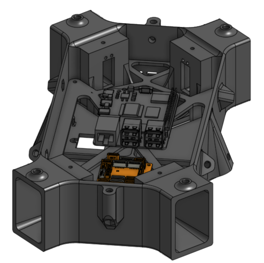
Power and signal separation
High-current motor and ESC paths are considered separately from low-level avionics signals. Central placement, harness access, and shielding interfaces guide the layout; EMI performance remains a verification task.
- Flight & navigation
- Flight controller · Dual-antenna RTK / UM982 design target
- Compute & communications
- Companion processing · Radio integration
- Propulsion & power
- Battery · Distribution · ESC / motor connections
Dual-antenna GNSS heading is a navigation design target. Companion-compute packaging must leave access for connections and heat removal; the pack enclosure includes vent openings. Thermal behavior and EMI separation still require installed-system checks.
Tray, shielding plate, and stiffener
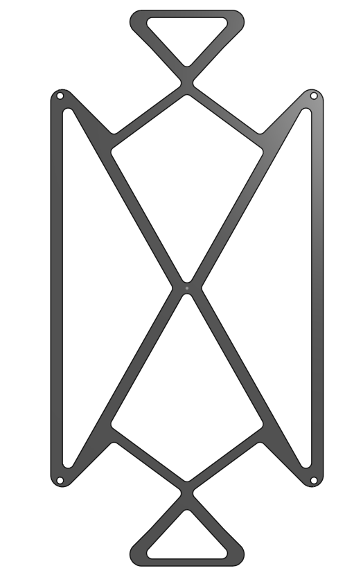
The internal mounting surface locates the avionics tray and shielding plate. The stiffener is intended to limit local deformation around the cavity. The documented FEA covers the main body only, so it does not establish tray or stiffener performance.
04 / Power system
Battery packaging and retention
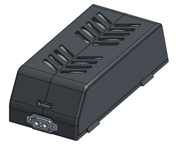
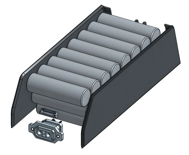
Munnin uses the same 6S4P, 21700-cell battery design used for Osiris, with 24 cells packaged inside a split enclosure. I designed the retention system alongside the body and top plate, with access to the pack and its mating connectors treated as mechanical requirements.
Enclosure
Separate left/right case and door components enclose the cells. Openings are included in the exterior geometry.
Retention
A spring latch and two compression springs form part of the updated assembly.
Connector access
The XT90NE-F panel-mounted power connector and separate JST-XH6-SMD connector are located at the end of the pack.
CAD reviewed in Battery → NEWBATASSEM on October 27, 2026. Electrical interconnects, latch capacity, and cooling performance are not established by these views.
05 / Structural engineering
Main-body inertial-relief analysis
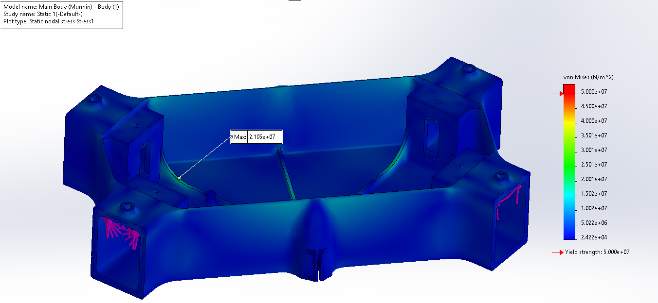
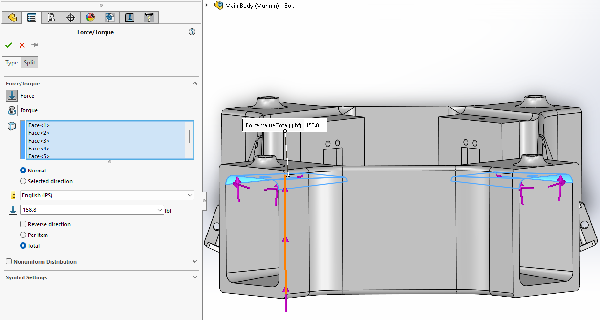
Preliminary SolidWorks FEA applies thrust and bending demand directly at the four arm interfaces. Inertial relief represents a free-flying body rather than a body held at a fixed structural boundary.
Load application
Per-arm thrust: 6 kgf × 9.80665 ≈ 58.8 N.
Bending demand: 58.8 N × 0.3048 m ≈ 17.9 N·m.
The equivalent motor moment arm is 12 inches.
Analysis boundary
Only the main body is covered. Battery and payload inertia, printed-material directionality, deflection acceptance, and hardware correlation remain necessary before using the result for final structural acceptance.
Load setup and material-definition assumptions
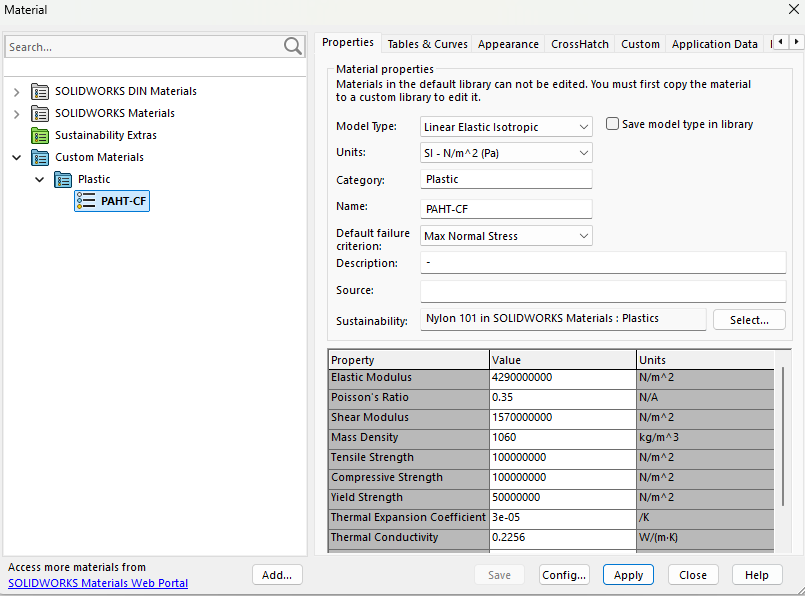
The review lists an elastic modulus of 4.29 GPa, Poisson’s ratio of 0.35, and density of 1060 kg/m³. Its material definition includes 100 MPa tensile/compressive values and 50 MPa yield. These are model inputs transcribed in the design review, not experimentally established printed-part allowables.
06 / Hardware status
Initial build
Physical assemblies are shown folded and extended. I coordinate fit, retention, harness access, and folding-interface checks as the team integrates the initial hardware.
- Built evidence
- Initial airframe hardware and the folded/extended configurations shown above.
- Design evidence
- Current battery CAD, earlier avionics packaging, and the documented preliminary main-body FEA.
- Next verification
- Installed-system checks, folding-lock behavior, landing-insert response, and structural correlation. Flight capability is not claimed from the CAD or FEA.
07 / Team apparel
Munnin shirt concept
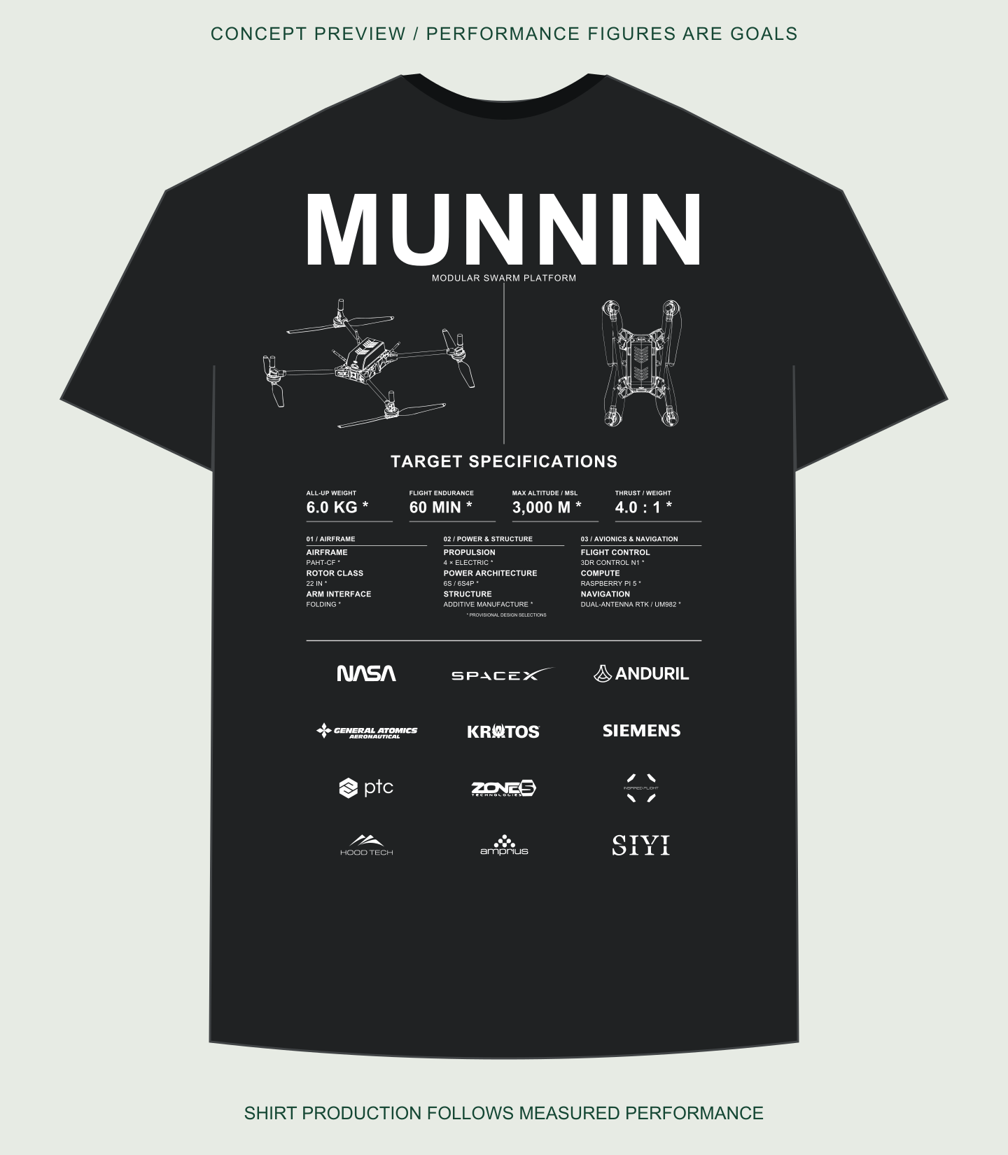
The artwork combines the aircraft’s extended and folded views with a technical specification layout. The displayed performance figures are design goals, including a 60-minute flight-time goal.
Production status
Shirts will be produced after aircraft performance has been measured and the printed specifications have been finalized. The rendering shows the proposed artwork.